
In creating our article, Climbing 101: Buying Cams, we realized that many novice climbers might already have some hands-on familiarity with them, but that there are still a lot of specific terms and phrases worth knowing.
Below is our glossary of terms to help give a better overview of the components and functions of cams. For more information on what to consider when making your first cam purchase, please see our Buying Cams article. And if you have suggestions for other terms that ought to be added to this glossary, let us know.
ACTIVE PLACEMENT: When a cam is situated in a crack such that the lobes are partially retracted and pushing outward on the walls of the crack. Cams are overwhelming used in this fashion, as opposed to passive placement.
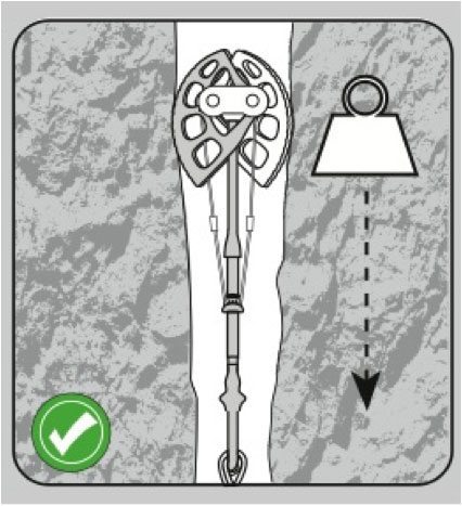
ACTIVE STRENGTH (or RATING): The magnitude of force that a cam has been tested and approved to withstand before complete device failure when used in the standard configuration (active placement), i.e. in an ideal placement inside a crack with the lobes pushing outward. Most full-size cams are rated in the 12-14kN range, though many smaller pieces are rated for smaller forces (often 6-8kN), or are only rated for aid climbing.
Cams and other forms of rock protection are typically certified as conforming to accepted standards of performance by an independent organization (such as the UIAA). Typically they are set in an ideal placement and an increasing amount of force is applied until the device fails (i.e. breaks). This identifies common failure modes as well as the magnitude of force the device can be expected to hold. Data from these experiments is distilled into a single value: the “active strength” of a device. The active strength of most cams is very robust compared to the forces experienced in typical climbing situations, however placements are often less optimal than the ideal achieved in the lab. Be attentive to these ratings as well as the quality of your placements, and always be aware of the limits of your gear.
AXLE: The axis of rotation for the lobes, the axle traverses the head of the cam and connects the lobes to the rest of a cam’s architecture.
Devices can be made with one axle, where all the lobes rotate about the same center point, or with two axles, where the two pairs of lobes rotate about two axles that sit slightly apart from one another.
CAM ANGLE: A numerical quantity describing how tight the curvature of a cam’s lobe is, which in turn affects how forces are transmitted during a fall. The cam angle also gives information about a cam’s range and holding power.
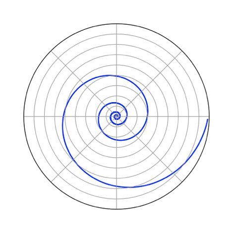 Cam lobes, across the board, are not round but are shaped as logarithmic spirals. This is the essential geometric factor that allows cams to transmit the downward force from a fall into outward force onto the sides of a crack.
Conveniently, logarithmic spirals are noted in the math world for having the property that the angle between the tangent and the radial line is constant for all points along the spiral. In other words, it’s this constant value that cam angle refers to. (Though in opposition to the standard practices in the academic world, the climbing universe is such that a smaller cam angle indicates a tighter spiral.)
The smaller the cam angle (and thus tighter the spiral), the greater the magnitude of the outward force applied per pound of downward force. But a smaller cam angle also means lobes pull inward quicker as the trigger is depressed, so they reach the end of their usable range (called simply “range”) faster. The result is that the usable range of a device and the magnitude of the force vector directed outward (called “holding power”) are inversely related: a tighter spiral (or smaller cam angle) means slightly more holding power, but slightly less range. The corollary is also true.
In practical terms, however, all cams populate a narrow range of cam angles, varying only slightly from one another across different brands. Consequently, both range and holding power are well within safe boundaries for any cam you might choose. Your preference, however, might lead you to prefer a certain cam angle over another.
CAM STOP: Cam stops broadly refer to any number of different mechanisms used by manufacturers to prevent the lobes from inverting (i.e. rotating in the wrong direction beyond their intended range of motion, like an umbrella turning inside out).
Cam stops can be brackets of metal that are part of the lobes themselves, which oppose each other when the cam is all the way open (as is the case in single axle designs) or, in double-axle designs, the opposing axle can function as a cam stop.

Some cam stops are there simply to prevent the lobes of the cam from inverting when the device is at rest, whereas others are robust enough to hold a fall. The latter allows a climber to place a cam passively, meaning it is placed as a stopper would be, pushing against a constriction in direct opposition to the rock rather than using the lobes to push outward against the walls of a crack as is the case during normal use.
HEAD: The business end of the cam, collectively denoting the lobes and axles of the device.
HEAD WIDTH: The dimension of the head of the cam that runs parallel to the axles, or perpendicular to the lobes. Head width is varied among cam brands and sizes and is an important consideration in certain placements. Climbers who find themselves protecting varied cracks or pin scars (such as in Yosemite) might place more of a premium on a cam having a narrow head width than would a fellow climber who typically climbs splitters (such as in the sandstone desert).
HOLDING POWER: The degree to which a cam transmits outward force as a product of downward force. It is generally the term that sits on the opposite side of the see-saw from “range” and is used to describe the relationship between range and outward force as determined by the cam angle.
LOBES: The active parts of the cam, these are the thin arcs of aluminum that actually contact the rock. The curved outer contact surfaces follow a logarithmic spiral (or a section of one, anyway), allowing the lobes to transmit a consistent outward force throughout the entire usable range of the cam.
PASSIVE PLACEMENT: A placement in which the device rests up against a constriction in the rock, as in the image below. The lobes are fully open, and the force of the fall is resisted by the cam stops, which prevent the lobes from inverting. This is analogous to the way a nut or stopper is placed.
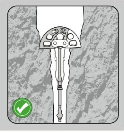
This is a different mode of operation than placing a cam actively (see Active Placement), and you must be sure that your cam is specifically rated for passive placements. Many cams have cams stops that are robust enough to permit passive placements, but not all. Be sure to check published specifications before using a cam in this way.
PASSIVE STRENGTH (or RATING): The magnitude of force that the cam has been tested and approved for when used as a stopper or chock. In this mode, the lobes are not depressed and the head of the cam pushes downward on a constriction. Just like with active strengths, exposing a passively placed cam to forces beyond those given in the rating will likely result in catastrophic device failure.
RATING: See Active and Passive Strength.
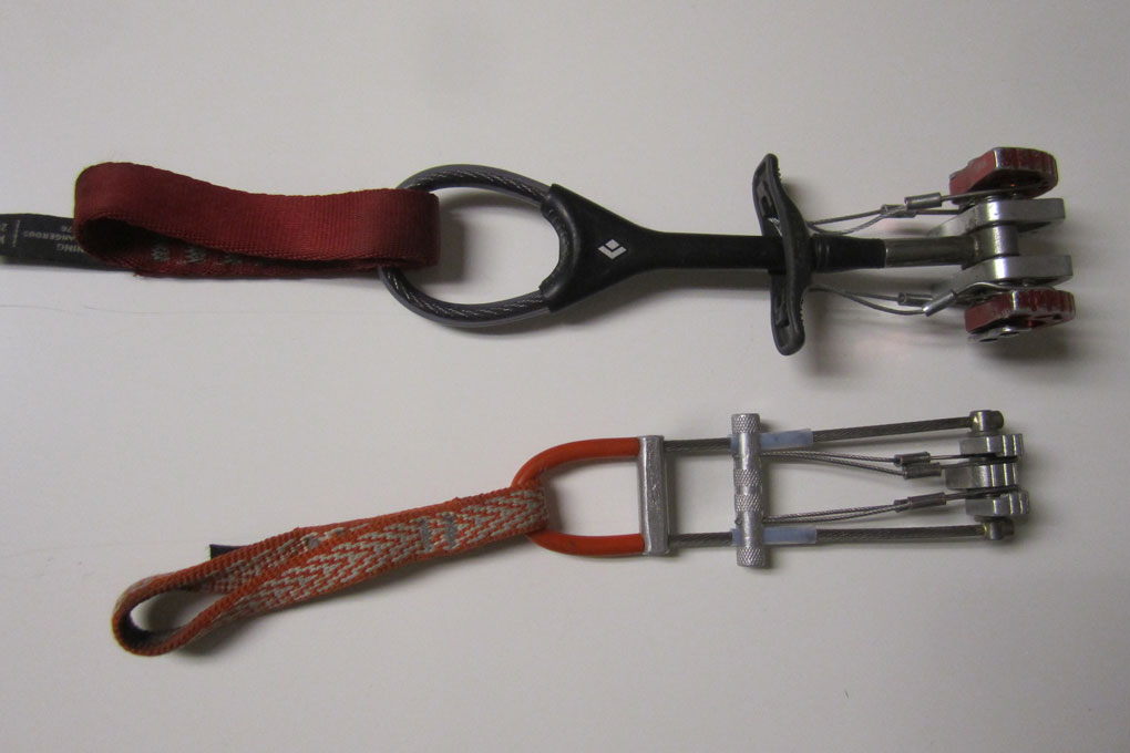
SINGLE-STEM: Design in which the head of the cam is supported by a single stem that bisects the axle, and connects the head of the cam to the sling at the opposite end.
TCU: An abbreviation that stands for Three Cam Unit, these are cams with three lobes rather than the typical four.
THUMB LOOP: A loop of coated cable (typically an extension of the stem) at the sling-end of the cam. Since cams are held like syringes, the thumb loop makes it easy to grab the cam and hold onto it when you are guiding it into a placement.
TRIGGER: The crossbar used to depress the lobes, connected to the lobes themselves via thin cables.
U-STEM: A design in which dual stems run in parallel down the outside of the device, coming together at the sling end of the cam in a “U” shape. This design allows for the heads to have three lobes, rather than four, which requires a lobe to sit in the center of the head in the space that would otherwise be occupied by the stem in a single-stem arrangement.
USABLE RANGE: Sometimes just “range,” this is the span of crack sizes an individual cam is suited for. It is important to choose the right size cam for a given placement, such that you avoid retracting the lobes of a cam too much or not enough, rendering the placement unsafe. The range of a cam denotes the sizes for which that particular device is appropriate.
For more information about what to consider when purchasing cams, see our Climbing 101: Buying Cams article